Chapter 1: System Components
Security Systems Lightning Protection and Grounding Design Guide
1.1 System Architecture
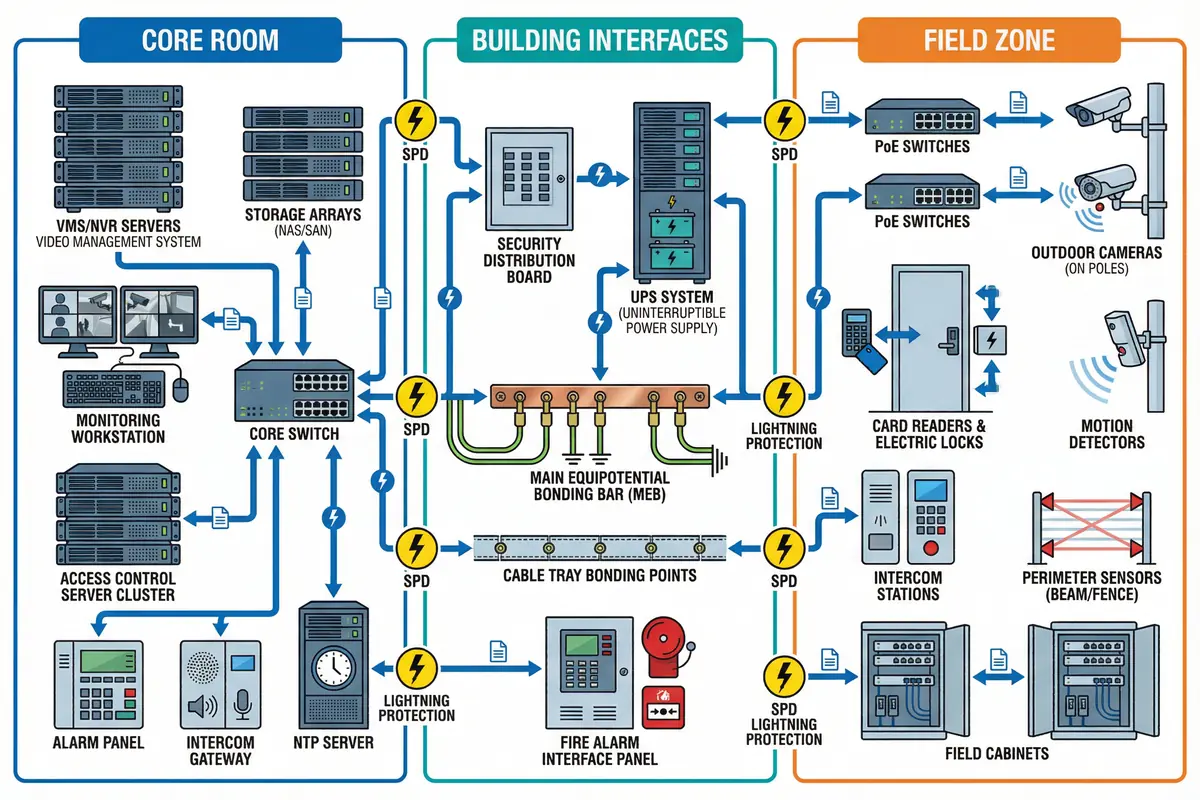
The security system lightning protection architecture is divided into three distinct zones, each with clearly defined equipment populations, interface boundaries, and surge control responsibilities. Understanding the relationship between these zones is essential for designing a coherent, testable protection strategy that eliminates gaps at every inter-zone boundary.
The Core Room zone houses all centralized processing, storage, and management equipment. The Building Interfaces zone contains the power distribution, bonding infrastructure, and fire/building system integration points. The Field Zone encompasses all outdoor and distributed endpoints that are most exposed to lightning-induced surges. Every connection crossing a zone boundary must be treated as a potential surge entry point and protected accordingly.
Module Relationships & Flows
Three primary flows connect the zones and define the protection requirements at each boundary. The power flow originates at the utility/distribution board, passes through Type 1/2 SPDs, the UPS for critical loads, and rack PDUs to reach IT and security devices. Field power follows a parallel path through cabinet SPDs to PoE switches or device power supplies. The data and control flow carries endpoint signals through access switches and field gateways to the core switch and then to VMS, ACS, and alarm servers. Alarm dry contacts route through the alarm panel to the management server, while intercom SIP/VoIP traffic passes through the intercom gateway. The surge control boundaries are defined at five critical points: the building service entrance, the security distribution board, the line entry to the weak-current room, the line entry to each field cabinet, and near sensitive ports on individual devices.
| Surge Control Boundary | Location | SPD Type Required | Primary Threat |
|---|---|---|---|
| Building Service Entrance | Main electrical panel | Type 1 (if required by risk) | Direct strike, GPR |
| Security Distribution Board | Weak-current room DB | Type 2 | Conducted surge from mains |
| Weak-Current Room Entry | Cable entry to core room | Type 2/3 + Ethernet SPD | Induced surge on copper runs |
| Field Cabinet Entry | Each outdoor cabinet | Type 2 (power) + data SPDs | Induced surge, direct exposure |
| Near Sensitive Ports | Device-level | Type 3 | Residual surge, port damage |
1.2 Components and Functions
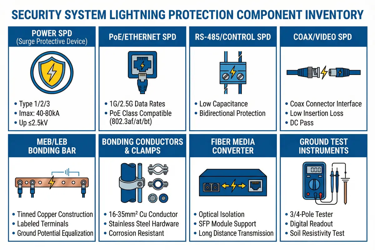
The complete component inventory spans three categories: core protection elements that are mandatory for every installation, optional enhancements that improve resilience or maintainability, and supporting infrastructure that the security system depends upon but does not own. Correct specification of each component requires understanding both its protective function and its interaction with adjacent components in the system.
| Component | Category | Primary Function | Key Specification | Acceptance Test |
|---|---|---|---|---|
| Power SPD (DB/Cabinet) | Core | Surge diversion for AC power lines; thermal disconnect; status indication | Uc ≥ 275 V; In 20–40 kA; Up ≤ 2.5 kV | Status indicator; Up coordination review |
| PoE/Ethernet SPD | Core | Protect data and PoE power on copper Ethernet; multi-pair protection | 1G/2.5G; PoE class compatible; low insertion loss | Link negotiation; PoE load test |
| RS-485/Control SPD | Core | Bidirectional protection for serial control lines; low capacitance | Clamping voltage per interface; <100 pF capacitance | Communication stability; polarity check |
| Coax/Video SPD | Core (legacy) | Protect coaxial video/control lines from induced surges | 75 Ω impedance match; BNC or F-type | Video signal quality; insertion loss |
| MEB/LEB Bonding Bar | Core | Equipotential bonding reference; labeled terminations for all bonded items | Tinned copper; rated current; labeled terminals | Continuity < 0.1 Ω; labeled as-built |
| Bonding Conductors & Clamps | Core | Low-impedance bonding paths; outdoor corrosion resistance | 16–35 mm² Cu; stainless/bimetal outdoor clamps | Continuity; torque; corrosion inspection |
| Fiber Media Converter | Optional/Core (high-risk) | Break conductive surge paths between buildings/zones; galvanic isolation | SFP or fixed; matching fiber type; enclosure bonded | OTDR; link loss; enclosure bonding check |
| Ground Test Instruments | Supporting | Measure grounding resistance and bonding continuity for acceptance and O&M | 3/4-pole ground tester; micro-ohmmeter | Calibration certificate; correct probe spacing |
Core vs. Optional vs. Supporting
A clear distinction between component categories prevents under-specification of mandatory items and helps prioritize budget allocation. Core components must be present in every compliant installation — their absence creates a measurable protection gap. Optional components provide incremental resilience improvements that are justified by site-specific risk factors such as high lightning ground flash density, coastal corrosion, or critical 24/7 operation requirements. Supporting components are infrastructure dependencies that the security system relies upon but that are owned and maintained by other building systems.
| Category | Components | Justification for Inclusion |
|---|---|---|
| Core (Mandatory) | MEB bonding, SPDs for power and major copper links, tray bonding, endpoint bonding, acceptance tests | Required for baseline protection; absence creates verifiable gap |
| Optional (Risk-Based) | Fiber isolation upgrades, remote SPD monitoring, transient recorders, enhanced ring electrode | Justified by high lightning density, critical operations, or coastal environment |
| Supporting (Dependency) | UPS, structured cabling, room earthing grid, fire/physical security interface | Owned by building/other systems; must be verified as compatible |
Design Principle: Every copper conductor entering a building, room, or cabinet is a potential surge entry path. The default design assumption should be that surge protection is required at every such entry point unless a specific engineering justification (e.g., fiber isolation) eliminates the need.