Security Systems Lightning Protection and Grounding Design Guide
A comprehensive, implementable engineering reference for protecting CCTV, access control, intrusion alarm, intercom, and perimeter detection systems against lightning effects and electromagnetic disturbances.
System Overview
This Security System Lightning Protection & Grounding Design Guide defines an implementable, testable engineering approach to protect CCTV, access control, intrusion alarm, intercom, and perimeter detection systems against lightning effects and electromagnetic disturbances. The core concept is to "build on the building lightning protection system" and then close the gaps introduced by security systems' characteristics: many endpoints, long cables, outdoor exposure, and high susceptibility to induced surges.
The guide addresses the full lifecycle from design and procurement through installation, acceptance testing, and ongoing operations and maintenance. It provides procurement-ready requirements for SPD selection, bonding conductors, grounding interfaces, routing rules, testing, and acceptance criteria — all grounded in verifiable engineering targets.
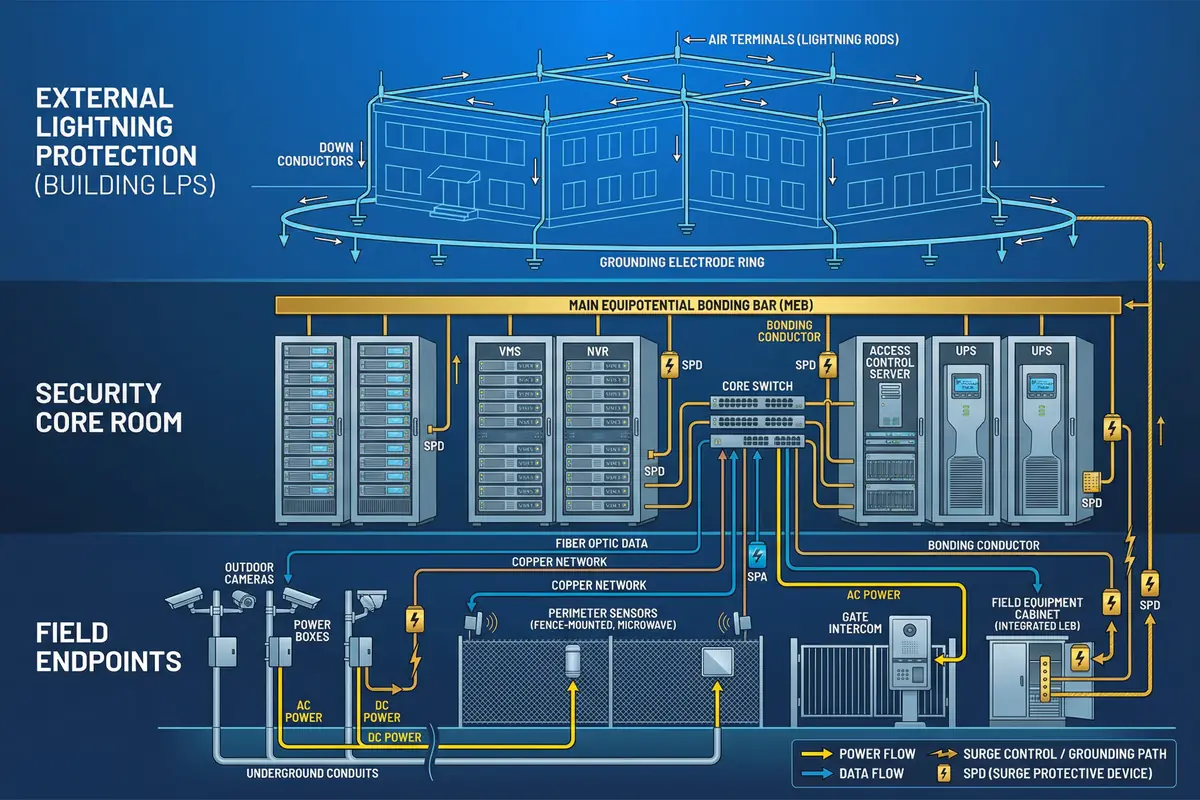
System Architecture
The overall architecture is organized in three horizontal layers, each with distinct responsibilities for managing lightning currents, surge energy, and electromagnetic coupling. The diagram below illustrates how the external lightning protection system, the security core room, and the field endpoints interact through coordinated bonding, SPD stages, and fiber isolation strategies.
Main Functions
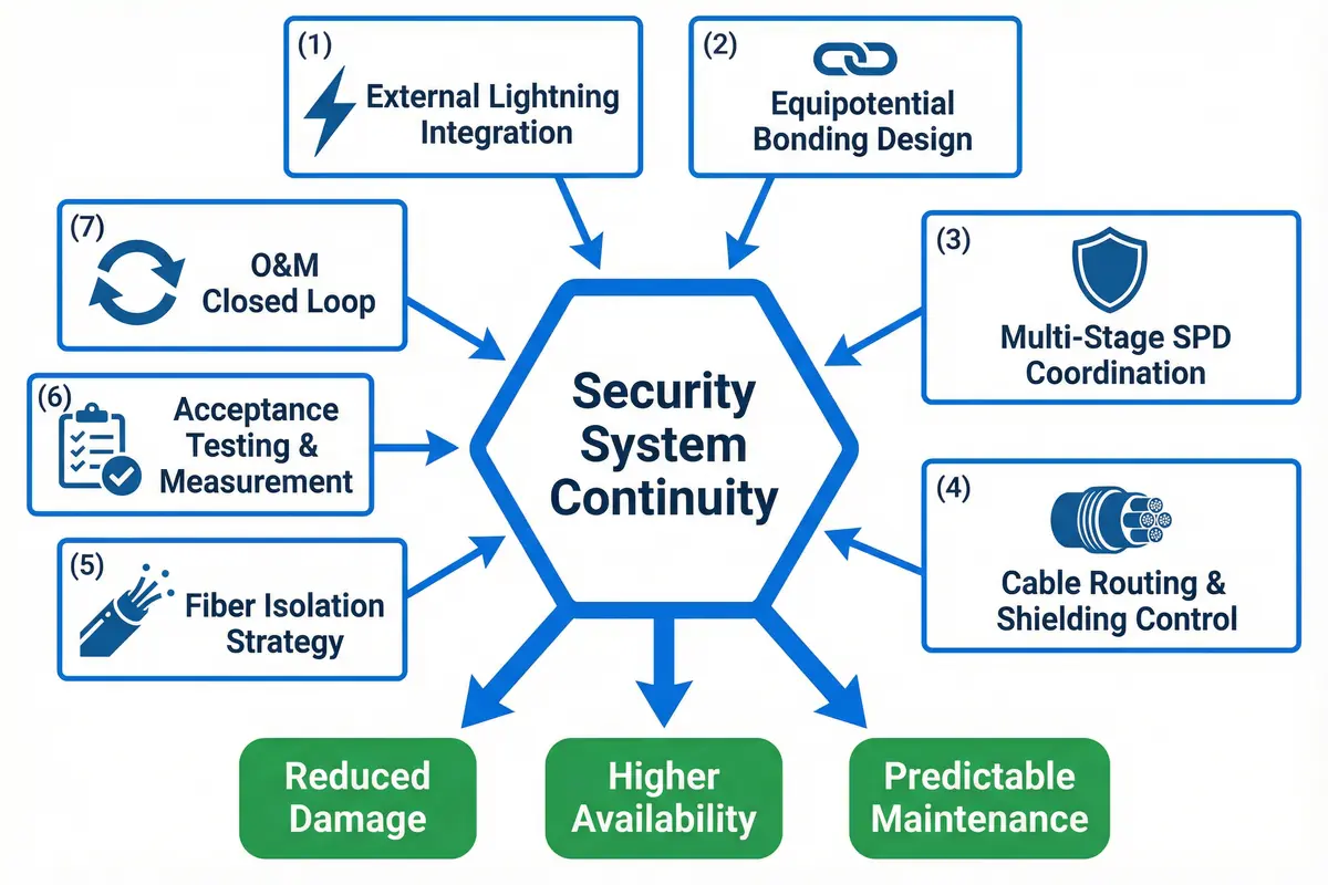
The guide is organized around seven core functional areas that together deliver security system continuity under lightning and surge conditions. Each function addresses a specific vulnerability in the typical security system installation, from the building's external lightning protection interface down to individual endpoint bonding and O&M closed-loop management.
Positioning & Goals: Reduce equipment damage and service interruption caused by direct strikes nearby, induced surges, switching transients, and ground potential rise (GPR). Ensure the security system remains stable, maintainable, and verifiable through design, installation, acceptance testing, and O&M routines.
Layered Responsibilities
| Layer | Primary Responsibility | Key Elements | Verification Focus |
|---|---|---|---|
| LPS & GES Layer | Provide low-impedance reference; manage direct lightning currents; limit GPR via bonding and electrode design | Air terminals, down conductors, ring earth electrode, MEB | Ground resistance ≤ 4 Ω; as-built drawings |
| Equipotential Bonding Layer | Reduce internal potential differences; bond racks, trays, metallic pipes, fences, poles, cabinets | MEB, TBB, LEB, bonding conductors, clamps | Continuity < 0.1 Ω; labeled terminations |
| Surge Protection Layer | Coordinated SPD stages (Type 1/2/3) protect power and signal/data/control lines at defined boundaries | Power SPDs, Ethernet SPDs, RS-485 SPDs, coax SPDs | Up coordination; SPD status; lead length |
| Shielding & Routing Layer | Reduce inductive coupling by separation, minimizing loop area, and correct shield termination strategy | Cable segregation, tray bonding, fiber isolation, 90° crossings | Route inspection; segregation; shield termination |
| Verification & O&M Layer | Test grounding resistance, bonding continuity, SPD status; seasonal inspection; post-event re-test | Test instruments, inspection schedule, incident workflow | Test reports; maintenance logs; MTTR targets |
Scope & Applicability
This guide covers cameras (pole/wall), NVR/VMS servers, switches, PoE injectors, access controllers, readers, electric locks, alarm panels, detectors, intercom masters/substations, perimeter sensors, field cabinets, outdoor poles/fences, and all associated power/network/control cabling. The boundary is defined at the interface with the building's external lightning protection system — this guide specifies how to bond and coordinate security subsystems with the existing LPS/GES, not how to redesign it.
Key Dependencies & Inputs
| Input / Dependency | Required Information | Verification Method |
|---|---|---|
| Building GES | Existing grounding electrode system, bonding points, resistance measurement | As-built drawings + fall-of-potential test report |
| Power System | 230/400 V AC feed, dedicated DB, UPS for critical loads | Single-line diagram + DB labeling + UPS nameplate |
| Network Topology | IP-based devices, legacy RS-485/coax coexistence, fiber demarcation points | Device BOM + interface list |
| Site Plan | Outdoor endpoint locations, cable routes, soil resistivity | Site plan + device coordinates |
| Local Standards | Applicable electrical and lightning standards (IEC, GB, local code) | Code reference list + AHJ confirmation |
Chapter Navigation
This guide is organized into twelve chapters covering the complete lifecycle of security system lightning protection — from system components and design methods through installation, quality acceptance, and ongoing operations and maintenance.