Chapter 8: Tools & Accessories
Security Systems Lightning Protection and Grounding Design Guide
8.1 Accessories & Tools Overview
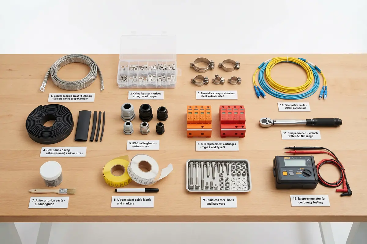
A complete security system lightning protection installation requires a range of accessories, consumables, and test instruments in addition to the primary SPD and bonding products. These items are often overlooked in initial procurement but are essential for achieving compliant installation quality, passing acceptance tests, and maintaining the protection system over its operational lifetime. The accessories list below is organized by category and includes the minimum quantity guidance for a typical medium-scale installation.
8.2 Accessories Bill of Materials
Bonding Conductors & Termination Hardware
| Item |
Specification |
Application |
Min Qty (Medium Site) |
Notes |
| Copper bonding conductor |
16 mm² Cu, green/yellow PVC, 100 m reel |
MEB/LEB to racks, trays, cabinets |
2 reels |
Cut to shortest path; no coils |
| Copper bonding conductor (heavy) |
25 mm² Cu, green/yellow PVC, 50 m reel |
MEB to GES; outdoor pole bonding |
1 reel |
For high-current paths |
| Copper braid bonding jumper |
50 mm² braid, 300 mm length, pre-terminated |
Cable tray joint bonding |
20 pcs per 100 m tray |
Pre-terminated for speed |
| Crimp cable lugs (16 mm²) |
DIN 46234; tin-plated copper |
Bonding conductor terminations |
50 pcs |
Match conductor size |
| Crimp cable lugs (25 mm²) |
DIN 46234; tin-plated copper |
Heavy bonding conductor terminations |
20 pcs |
Match conductor size |
| Hydraulic crimp tool |
16–95 mm² range; hex dies |
Crimping cable lugs |
1 set |
Calibrated; correct die set |
Bonding Clamps & Connectors
| Item |
Specification |
Application |
Min Qty (Medium Site) |
Notes |
| Bimetal bonding clamp (pole) |
Stainless steel body; copper contact; 50–100 mm range |
Steel pole to copper conductor bonding |
Per pole count |
Bimetal prevents galvanic corrosion |
| Bimetal bonding clamp (fence) |
Stainless steel body; copper contact; 25–50 mm range |
Fence section bonding |
Per fence section count |
316L SS for coastal sites |
| Cable tray bonding clamp |
Zinc-plated steel; spring-loaded; fits standard tray rail |
Conductor to tray rail bonding |
2 per tray section |
No drilling required |
| Anti-corrosion paste |
Zinc-based; outdoor-rated; 500 g jar |
All outdoor bonding connections |
2 jars per site |
Apply before final torque |
| Stainless steel fasteners |
M8 × 20 mm; A4 316L SS; hex head |
Outdoor bonding connections |
50 pcs |
Do not mix with carbon steel |
SPD Accessories & Mounting Hardware
| Item |
Specification |
Application |
Min Qty (Medium Site) |
Notes |
| DIN rail (35 mm) |
EN 60715; 1 m length; galvanized steel |
SPD and CB mounting in cabinets |
Per cabinet count |
Bond rail to LEB |
| SPD replacement cartridges |
Match installed SPD model |
Post-event replacement spares |
20% of installed count |
Critical for fast recovery |
| Ethernet SPD spare modules |
Match installed model; 1G or 2.5G |
Post-event replacement spares |
10% of installed count |
Store in dry location |
| Cable glands (M20/M25) |
IP68; nickel-plated brass; EMC version |
Cable entry sealing in outdoor cabinets |
Per cable entry count |
EMC glands for shielded cables |
| Door bonding strap |
Copper braid; 200 mm; pre-terminated |
Cabinet door to body bonding |
Per cabinet count |
Replace if cracked or corroded |
Test Instruments
| Instrument |
Specification |
Application |
Calibration Requirement |
Notes |
| Ground resistance tester |
3/4-pole; 0.01–2000 Ω range; IEC 61557-5 |
Grounding electrode resistance measurement |
Annual calibration |
Correct probe spacing critical |
| Micro-ohmmeter |
0.1 µΩ–2000 Ω; 4-wire Kelvin; 10 A test current |
Bond continuity measurement (< 0.1 Ω) |
Annual calibration |
4-wire eliminates lead resistance |
| Clamp-on ground tester |
Non-intrusive; 0.01–1200 Ω; IEC 61557-5 |
Ground resistance without disconnection |
Annual calibration |
Useful for in-service checks |
| Insulation resistance tester |
500/1000 V DC; 0.01 MΩ–10 GΩ |
Cable insulation integrity check |
Annual calibration |
Disconnect sensitive equipment before test |
| Network cable tester |
Cat5e/Cat6/Cat6A; wiremap + length + PoE test |
Ethernet link verification after SPD installation |
Functional check |
Verify PoE pass-through |
| Torque wrench |
5–50 Nm; calibrated; 3/8" drive |
Bonding connection torque verification |
Annual calibration |
Record torque values in commissioning log |
Documentation & Labeling
| Item |
Specification |
Application |
Notes |
| Cable labels (self-laminating) |
UV-resistant; 50 × 25 mm; printable |
Cable identification at both ends |
Match cable schedule |
| SPD location labels |
Brady or equivalent; weatherproof |
SPD identification and circuit reference |
Include replacement cartridge model |
| Bonding conductor labels |
Green/yellow; heat-shrink sleeve |
Bonding conductor identification |
Apply at both termination ends |
| Test point markers |
Stainless steel tag; engraved ID |
Ground test point identification |
Permanent; weather-resistant |
| As-built drawing holder |
Weatherproof A3 sleeve; wall-mount |
On-site drawing storage in equipment room |
Include latest revision date |
Procurement Tip: SPD replacement cartridges and Ethernet SPD spare modules should be included in the initial procurement order and stored on site. Post-storm replacement is time-critical — having spares on site reduces mean time to recovery from days (waiting for delivery) to hours (immediate replacement). Specify a minimum 20% spare ratio for power SPD cartridges and 10% for data SPD modules.