Chapter 7: Support & Integration
Security Systems Lightning Protection and Grounding Design Guide
7.1 Support Systems Overview
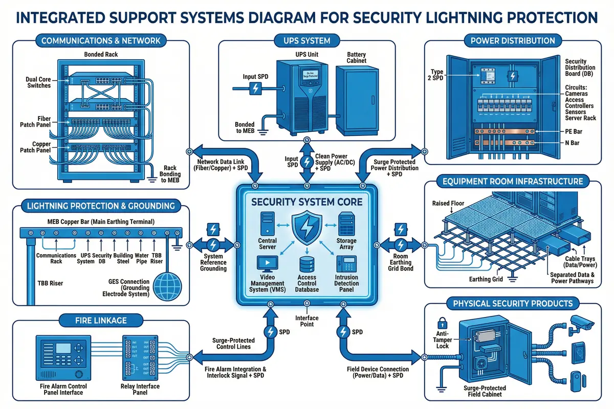
Security system lightning protection does not operate in isolation — it depends on, and must be coordinated with, a range of supporting systems and infrastructure elements that are typically owned and maintained by other teams. These supporting systems include the building's electrical distribution, uninterruptible power supply, structured cabling, grounding electrode system, and building management system. Failure to coordinate with these systems is a common cause of protection gaps, acceptance failures, and post-installation disputes.
The integrated support systems diagram below shows all supporting equipment categories in a single view, illustrating their relationships to the security system's lightning protection elements. This integrated view is essential for identifying interface boundaries, clarifying responsibilities, and ensuring that every dependency is addressed in the design and procurement process.
7.2 Support System Requirements
Each supporting system category has specific requirements that must be verified before the security system lightning protection design can be finalized. These requirements define the interface conditions that the protection design depends upon, and deviations from these requirements may require design modifications or additional protection measures.
Electrical Distribution & UPS
The security system's power supply chain begins at the building's electrical distribution board and must include a dedicated circuit for the security system, a Type 2 SPD at the distribution board, and a UPS for critical loads. The UPS provides both surge isolation (its input SPD and internal filtering) and backup power continuity during outages. The UPS output is a clean power source that should not require additional SPD protection, but the UPS input must be protected by a Type 2 SPD upstream.
- Dedicated security system circuit breaker at DB (prevents nuisance tripping from other loads)
- Type 2 SPD at security DB upstream of UPS input (protects UPS from conducted surges)
- UPS for all critical loads: NVR, VMS, core switch, alarm panel (maintains operation during outages)
- UPS bypass switch for maintenance (enables SPD replacement without system downtime)
- UPS battery test schedule aligned with O&M plan (ensures backup capacity is available)
- UPS output power quality monitoring (detects input SPD degradation through output quality changes)
Structured Cabling & Cable Management
The structured cabling system provides the physical infrastructure for security system data connections. Its design must support the lightning protection strategy by maintaining required separation distances between power and data cables, providing bonded metallic cable trays for shielding, and accommodating fiber links at inter-building boundaries. Cabling changes after the initial installation must go through a change management process to prevent inadvertent introduction of new surge paths.
- Metallic cable trays bonded to MEB/LEB at regular intervals (provides shielding and equipotential path)
- Separate trays for power and data cables with required separation distance maintained
- Fiber links at all inter-building and inter-zone boundaries (eliminates surge paths)
- Cable entry points sealed and documented (prevents unauthorized copper runs bypassing fiber isolation)
- Cable labeling consistent with SPD location map (supports maintenance and troubleshooting)
- As-built cabling drawings updated after any modification (maintains accurate protection documentation)
Grounding Electrode System (GES)
The building's grounding electrode system is the foundation of the entire lightning protection strategy. The security system's protection measures are only effective if the GES provides a low-impedance path to earth for surge current diversion. The GES must be verified before the security system design is finalized, and any deficiencies must be corrected before commissioning.
- Ground resistance ≤ 4 Ω (or local code requirement) verified by fall-of-potential test
- MEB bonded to GES with test link for periodic resistance measurement
- Electrode system documented in as-built drawings with test point locations
- Seasonal ground resistance test (soil resistivity changes with moisture content)
- Electrode enhancement (additional rods, ground enhancement material) if resistance target not met
- Coordination with building structural steel bonding (structural steel is a valuable natural electrode)
Building Management System (BMS) Integration
Integration of SPD monitoring with the building management system enables proactive maintenance by providing real-time visibility of SPD status across the entire installation. This integration is particularly valuable for large installations with many field cabinets, where manual inspection of every SPD after each storm event would be impractical. The BMS integration should provide SPD fault alarms, event logging, and maintenance scheduling support.
- SPD remote alarm contacts wired to BMS I/O modules (enables real-time fault detection)
- SPD fault events logged with timestamp and location (supports root cause analysis)
- Maintenance alert generated when SPD enters fault state (triggers replacement workflow)
- Ground resistance test results recorded in BMS (provides trend data for electrode maintenance)
- Post-storm inspection workflow triggered by BMS event log (ensures systematic post-event response)
- Annual inspection schedule managed through BMS work order system (prevents inspection gaps)
7.3 Integration Requirements Summary
| Support System | Interface Requirement | Verification Method | Responsibility | Inspection Frequency |
|---|---|---|---|---|
| Electrical distribution | Dedicated CB + Type 2 SPD at DB | Single-line diagram review + inspection | Electrical contractor | Annual |
| UPS system | Critical loads on UPS; SPD upstream | UPS load test + battery capacity test | Security contractor + UPS supplier | 6-monthly battery test; annual full test |
| Structured cabling | Bonded trays; fiber at boundaries; separation maintained | Physical inspection + continuity test | Cabling contractor | Annual + after modifications |
| Grounding electrode system | R_E ≤ 4 Ω; MEB bonded with test link | Fall-of-potential test | Electrical contractor + building owner | Annual (pre-storm season) |
| BMS integration | SPD alarm contacts wired; events logged | BMS point list verification; alarm test | BMS contractor + security contractor | Annual functional test |
| Fire system interface | Shared cable routes coordinated; no interference | Route inspection; interference test | Fire contractor + security contractor | Annual |
Coordination Requirement: The grounding electrode system must be verified by fall-of-potential test before the security system commissioning begins. If the measured resistance exceeds the design target, the security system commissioning should be deferred until the GES is enhanced to meet the target. Commissioning on a non-compliant GES creates a documented protection gap that may be difficult to remediate after the system is in operation.