Chapter 10: Quality & Acceptance
Security Systems Lightning Protection and Grounding Design Guide
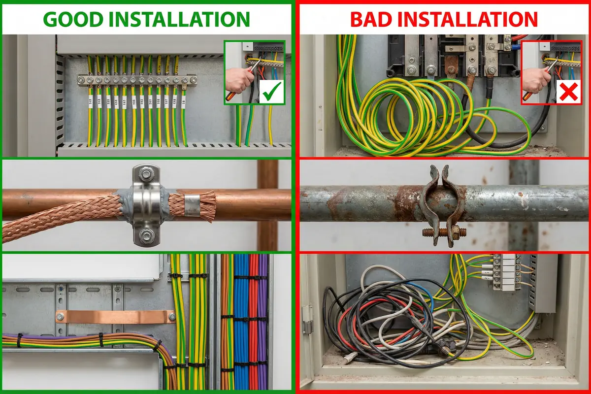
10.1 Quality Comparison: Compliant vs. Non-Compliant Installation
The quality of a security system lightning protection installation can vary dramatically depending on the workmanship, material quality, and adherence to design specifications. The photograph below illustrates the key visual differences between a compliant, high-quality installation and a non-compliant installation with common defects. These differences are not merely aesthetic — each defect represents a measurable reduction in protection effectiveness that will manifest as equipment damage during the next significant storm event.
Quality control during installation is significantly more cost-effective than post-damage remediation. The cost of replacing a single NVR or network switch typically exceeds the cost of the SPD and bonding materials that would have prevented the damage. Systematic inspection using the checklist in Section 10.3 ensures that quality issues are identified and corrected before commissioning, not after the first storm.
10.2 Acceptance Test Procedures
Acceptance testing for security system lightning protection is organized into four test groups that must be completed in sequence. Each test group builds on the results of the previous group — it is not meaningful to test SPD coordination before verifying that the bonding and grounding infrastructure is compliant. The test sequence reflects the physical hierarchy of the protection system, from the grounding electrode system at the foundation through to the device-level functional tests at the top.
Test Group 1: Grounding Electrode System
| Test | Method | Pass Criterion | Instrument | Documentation |
|---|---|---|---|---|
| Ground resistance (main GES) | 3/4-pole fall-of-potential; correct probe spacing | R_E ≤ 4 Ω (or local code) | Ground resistance tester (calibrated) | Test report with probe positions, soil conditions, date |
| Ground resistance (field poles) | 3-pole fall-of-potential at each pole | R_E ≤ 10 Ω (remote sites) | Ground resistance tester | Test report per pole; GPS coordinates |
| MEB to GES continuity | 4-wire micro-ohmmeter; test link disconnected | < 0.1 Ω | Micro-ohmmeter (calibrated) | Test report; photo of test link position |
| Test link accessibility | Visual inspection | Accessible; labeled; disconnectable | Visual | Photo |
Test Group 2: Equipotential Bonding
| Test | Method | Pass Criterion | Instrument | Documentation |
|---|---|---|---|---|
| Equipment rack to MEB | 4-wire micro-ohmmeter; rack frame to MEB terminal | < 0.1 Ω per bond | Micro-ohmmeter | Test report; photo of each connection |
| Cable tray continuity | 4-wire micro-ohmmeter; end-to-end along tray run | < 0.1 Ω end-to-end | Micro-ohmmeter | Test report; tray run identification |
| Field cabinet to LEB | 4-wire micro-ohmmeter; cabinet body to LEB | < 0.1 Ω | Micro-ohmmeter | Test report per cabinet |
| Outdoor pole to GES | 4-wire micro-ohmmeter; pole base to GES | < 0.1 Ω | Micro-ohmmeter | Test report per pole |
| SPD earth lead length | Physical measurement | ≤ 0.5 m preferred; no coils | Tape measure | Photo; note any exceptions |
| Bonding conductor labeling | Visual inspection against as-built drawings | All conductors labeled at both ends | Visual | Photo; checklist |
Test Group 3: SPD Installation & Coordination
| Test | Method | Pass Criterion | Instrument | Documentation |
|---|---|---|---|---|
| SPD location vs. design | Compare as-built to SPD location map | All specified SPDs installed at correct locations | Visual + drawings | Marked-up as-built drawing |
| SPD status indicators | Visual inspection of all SPD status indicators | All indicators show normal/green status | Visual | Photo of each SPD panel |
| SPD Up coordination | Datasheet review; compare Up values Type 1→2→3 | Up decreasing; Type 3 Up < equipment Uw | Datasheets | SPD schedule with Up values |
| PoE SPD compatibility | PoE load test at full port count | No PoE drops; link at correct speed | PoE tester / switch port statistics | Test report; port statistics screenshot |
| Data SPD insertion loss | Link speed negotiation check; error counter | Link at correct speed; error counter < threshold | Network switch CLI | Screenshot of port statistics |
Test Group 4: System Functional Tests
| Test | Method | Pass Criterion | Instrument | Documentation |
|---|---|---|---|---|
| Network performance | iPerf throughput test; ping latency test | Throughput ≥ design spec; latency within spec | iPerf; ping | Test report with results |
| Video quality baseline | Visual inspection of all camera feeds | No interference patterns; correct resolution | VMS client | Screenshot per camera |
| Alarm system baseline | Monitor false alarm rate over 7-day period | False alarm rate within project KPI | Alarm management system | Alarm event log report |
| Cable routing inspection | Physical inspection of all cable routes | Separation maintained; no unauthorized copper runs | Visual + tape measure | Inspection checklist; photos of exceptions |
| Documentation completeness | Document audit against required list | All required documents present and current | Document checklist | Document register |
10.3 Acceptance Checklist Summary
The acceptance checklist provides a structured record of all acceptance test results, enabling the project team to track progress toward commissioning and identify outstanding items. The checklist must be completed by a qualified engineer and signed off by both the installing contractor and the client representative before the system is handed over for operation.
| # | Acceptance Item | Pass Criterion | Status |
|---|---|---|---|
| 1 | Ground resistance (main GES) | R_E ≤ 4 Ω | [ ] Pass [ ] Fail [ ] N/A |
| 2 | Ground resistance (field poles) | R_E ≤ 10 Ω | [ ] Pass [ ] Fail [ ] N/A |
| 3 | MEB to GES continuity | < 0.1 Ω | [ ] Pass [ ] Fail [ ] N/A |
| 4 | Equipment rack bonding continuity | < 0.1 Ω per bond | [ ] Pass [ ] Fail [ ] N/A |
| 5 | Cable tray continuity | < 0.1 Ω end-to-end | [ ] Pass [ ] Fail [ ] N/A |
| 6 | Field cabinet bonding continuity | < 0.1 Ω | [ ] Pass [ ] Fail [ ] N/A |
| 7 | Outdoor pole bonding continuity | < 0.1 Ω | [ ] Pass [ ] Fail [ ] N/A |
| 8 | SPD earth lead length | ≤ 0.5 m; no coils | [ ] Pass [ ] Fail [ ] N/A |
| 9 | All SPDs installed per design | Location map match | [ ] Pass [ ] Fail [ ] N/A |
| 10 | All SPD status indicators normal | All green/normal | [ ] Pass [ ] Fail [ ] N/A |
| 11 | SPD Up coordination verified | Decreasing Type 1→2→3 | [ ] Pass [ ] Fail [ ] N/A |
| 12 | PoE SPD compatibility | No drops; correct speed | [ ] Pass [ ] Fail [ ] N/A |
| 13 | Network performance | Throughput and latency within spec | [ ] Pass [ ] Fail [ ] N/A |
| 14 | Video quality baseline | No interference | [ ] Pass [ ] Fail [ ] N/A |
| 15 | Alarm false alarm rate baseline | Within project KPI | [ ] Pass [ ] Fail [ ] N/A |
| 16 | Cable routing inspection | Separation maintained | [ ] Pass [ ] Fail [ ] N/A |
| 17 | Bonding conductor labeling | All labeled at both ends | [ ] Pass [ ] Fail [ ] N/A |
| 18 | As-built documentation complete | All documents present | [ ] Pass [ ] Fail [ ] N/A |
Acceptance Principle: All items in the acceptance checklist must achieve "Pass" status before the system is handed over. "Fail" items must be corrected and re-tested. "N/A" items must be justified in writing. Partial acceptance (accepting a system with outstanding "Fail" items) creates documented liability for the installing contractor and unacceptable risk for the client.