Chapter 11: Installation & Debugging
Security Systems Lightning Protection and Grounding Design Guide
11.1 Installation Requirements
The installation of security system lightning protection components requires careful attention to workmanship quality, material compatibility, and adherence to the design specifications. The most common cause of protection failure is not incorrect design but incorrect installation — particularly long SPD earth leads, missing bonding jumpers, and corroded outdoor connections that are not visible during normal operation. The following installation requirements define the minimum quality standards for a compliant installation.
11.2 Installation Method Statements
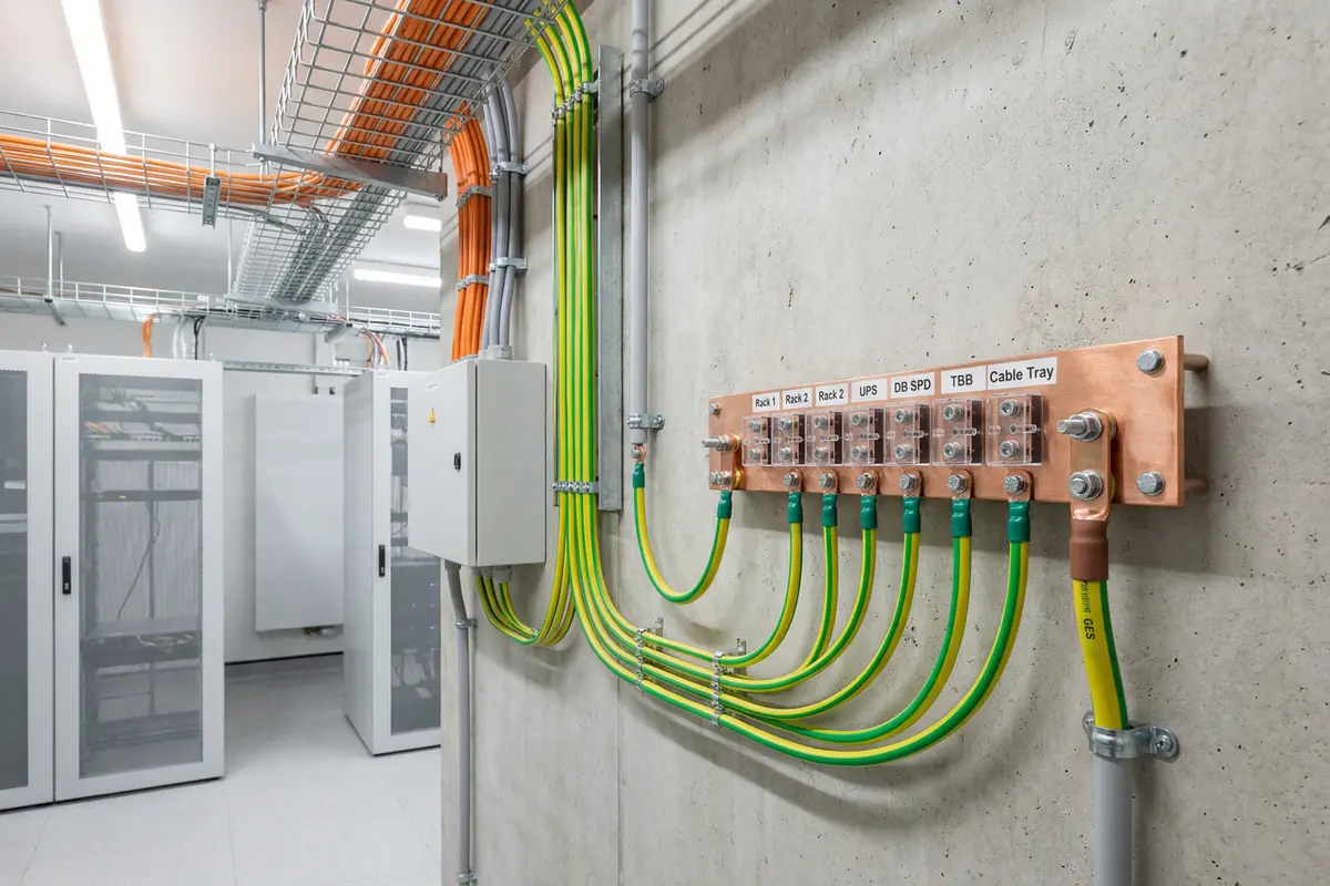
MEB and LEB Installation
- Mount MEB at the entry point of the weak-current room, as close as possible to the GES connection point
- Use tinned copper bar with labeled terminal positions; minimum 25 × 5 mm cross-section
- Connect MEB to GES with ≥ 25 mm² Cu conductor via a test link that can be disconnected for resistance measurement
- Label the test link clearly: "GROUNDING TEST LINK — DO NOT DISCONNECT EXCEPT FOR TESTING"
- Bond all equipment racks, UPS enclosures, and cable trays to MEB with ≥ 16 mm² Cu conductors
- Keep all bonding conductors as short and straight as possible — no coils, no sharp bends
- Label all bonding conductors at both termination ends with green/yellow heat-shrink sleeves
- Photograph all MEB connections before closing cable trays or conduits
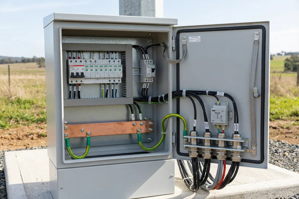
SPD Installation
- Install SPD at the cable entry point, not downstream of the entry — the SPD must intercept the surge before it reaches any equipment
- Keep SPD earth lead as short as possible; ≤ 0.5 m is strongly preferred; never coil the earth lead
- Connect SPD earth terminal directly to the nearest LEB terminal with a dedicated conductor — do not daisy-chain SPD earth leads
- Verify SPD Uc rating matches the system voltage before installation
- Verify PoE SPD current rating matches the PSE output class before installation
- Verify data SPD data rate compatibility before installation (test link speed after installation)
- Check SPD status indicator after installation and before energizing connected equipment
- Label each SPD with its circuit reference, installation date, and replacement cartridge model number
- Record SPD installation in the commissioning log with location, model, and serial number
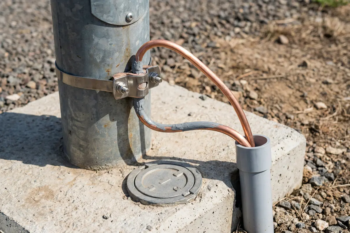
Outdoor Bonding & Grounding
- Use bimetal clamps for all connections between copper conductors and steel poles or structures — never use standard copper clamps on steel (galvanic corrosion)
- Apply anti-corrosion paste to all outdoor bonding connections before final torque
- Protect outdoor bonding conductors with UV-resistant conduit where exposed to sunlight
- Install test point access covers at all pole base grounding connections for periodic resistance testing
- Use 316L stainless steel fasteners for all outdoor connections in coastal or corrosive environments
- Photograph all outdoor bonding connections before backfilling or covering with concrete
- Record GPS coordinates and test point locations in the as-built documentation
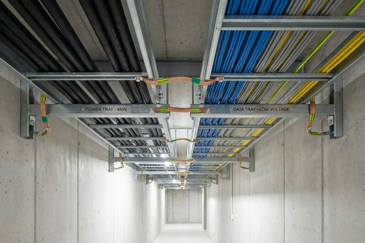
Cable Routing & Tray Bonding
- Maintain required separation distance from lightning protection down conductors throughout the cable route
- Use separate cable trays for power and data cables; maintain required separation between trays
- Install bonding jumpers at every cable tray joint using pre-terminated copper braid jumpers
- Bond cable tray to building structure or MEB/LEB at regular intervals (maximum 30 m)
- Where cables must cross down conductors, cross at 90 degrees
- Document all cable routes in as-built drawings, noting separation distances at critical points
- Seal all cable entry points into buildings and cabinets after installation
11.3 Debugging Guide
The debugging process for security system lightning protection issues follows a systematic diagnostic approach that starts with the most fundamental elements (grounding and bonding) and works upward through the protection layers to the system-level symptoms. Attempting to debug system-level symptoms without first verifying the foundation layers is a common cause of wasted diagnostic effort.
| Symptom | Diagnostic Step | Root Cause | Fix | Verification |
|---|---|---|---|---|
| Repeated device failures after storms | 1. Check SPD status; 2. Measure ground resistance; 3. Check bonding continuity | Failed SPD not replaced; high ground resistance; missing bonding | Replace SPDs; enhance GES; add missing bonds | Ground test; continuity test; SPD status normal |
| Persistent false alarms | 1. Check shield termination; 2. Check cabinet bonding; 3. Check cable routing | Ground loop from incorrect shield grounding; EMI from poor routing | Correct shield termination; bond cabinet to LEB; reroute cables | False alarm rate returns to baseline |
| Intermittent video loss | 1. Check Ethernet SPD compatibility; 2. Check PoE current; 3. Check link error counters | SPD insertion loss too high; PoE current limit; EMI on cable | Replace with compatible SPD; correct PoE class; improve routing | Link stable; error counters zero; video continuous |
| High ground resistance | 1. Verify probe spacing; 2. Check electrode connections; 3. Check soil moisture | Incorrect test method; corroded electrode connection; dry soil | Correct test method; clean/replace connection; add electrodes or GEM | Resistance ≤ 4 Ω; documented test report |
| Bond continuity fail | 1. Locate high-resistance joint; 2. Inspect visually for corrosion or loose lug | Corroded clamp; loose crimp lug; missing jumper | Replace corroded hardware; retorque or re-crimp; add missing jumper | Continuity < 0.1 Ω |
| PoE port resets after SPD installation | 1. Check SPD PoE class rating; 2. Measure port current | SPD PoE current rating insufficient for load | Replace with correctly rated PoE SPD | Port stable; no resets under full load |
| Access control communication errors | 1. Check RS-485 SPD capacitance; 2. Check polarity; 3. Check termination resistors | High capacitance SPD; reversed polarity; incorrect termination | Replace with low-capacitance SPD; correct polarity; check termination | Communication stable; error rate zero |
11.4 Common Installation Errors & Prevention
| Error | Detection Method | Prevention |
|---|---|---|
| SPD installed downstream of cable entry | Route inspection; compare to design | Mark entry points on design drawings; inspect before cabling |
| SPD earth lead coiled or > 0.5 m | Visual inspection; tape measure | Method statement specifying max lead length; photo checklist |
| Missing tray bonding jumper at joint | Continuity test along tray run | Specify jumpers in tray specification; inspect before cable installation |
| Standard copper clamp on steel pole | Visual inspection; material check | Specify bimetal clamps in procurement; inspect on delivery |
| Anti-corrosion paste not applied | Visual inspection before final torque | Method statement; photo checklist before torque |
| Wrong PoE SPD class installed | PoE load test; port statistics | Verify PoE class in procurement spec; check label before installation |
| RS-485 SPD polarity reversed | Communication test after installation | Wiring diagram on SPD label; verify before energizing |
| Fiber link bypassed with copper during commissioning | Topology audit; as-built review | Change management procedure; as-built update required for any change |
Safety Warning: All grounding and bonding work must be performed with the relevant circuits de-energized where required by local electrical safety regulations. Ground resistance testing requires correct probe spacing and must be performed by a qualified person. SPD replacement must be performed with the protected circuit de-energized unless the SPD design specifically permits hot-swap replacement.