Chapter 4: Architecture Design
Security Systems Lightning Protection and Grounding Design Guide
4.1 Typical System Topology
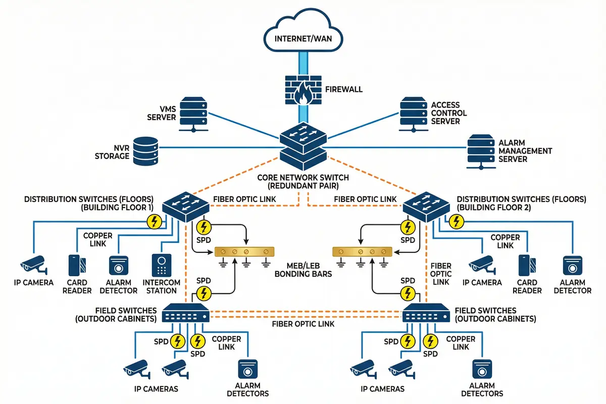
The typical security system lightning protection architecture follows a hierarchical network topology that places fiber optic links at every inter-building and inter-zone boundary, reserving copper connections for the final segment between field cabinets and end devices. This "fiber-first" topology eliminates the most significant surge paths — long outdoor copper runs between buildings — while maintaining the cost-effectiveness of copper for short indoor and cabinet-level connections.
The topology diagram below illustrates the complete system from the WAN/internet boundary through the core network layer, distribution switches on building floors, field switches in outdoor cabinets, and finally to end devices. SPD symbols are shown at every copper link entry point, and MEB/LEB bonding bars are shown at the core room and each field cabinet. Fiber links are shown as dashed lines to distinguish them from copper links, which require SPD protection.
Topology Design Principles
The topology design is governed by five principles that together minimize surge risk while maintaining network performance and maintainability. First, fiber is used for all inter-building and inter-zone links, eliminating the most energetic surge paths. Second, copper links are limited to short runs within a single zone, where induced surge energy is lower and SPD protection is more effective. Third, redundant core switches with ring topology provide path diversity for both normal traffic and post-surge recovery. Fourth, field cabinets serve as the primary surge control boundary for their associated endpoints, with LEB bonding and SPD protection for all incoming lines. Fifth, the topology supports remote SPD monitoring, enabling proactive maintenance before the next storm event.
| Network Layer | Equipment | Link Type | SPD Required | Bonding Requirement |
|---|---|---|---|---|
| Core (Equipment Room) | VMS server, NVR, core switch (redundant pair), access control server, alarm server | Fiber uplinks; copper to DB/UPS | Type 2 at DB; Type 3 at rack PDU | All racks to MEB; trays to MEB |
| Distribution (Building Floors) | Distribution switches, patch panels, floor LEBs | Fiber from core; copper to endpoints | Ethernet SPD at copper entry | Switch racks to LEB; trays to LEB |
| Field (Outdoor Cabinets) | PoE switches, media converters, field LEBs, Type 2 SPDs | Fiber from building; copper to devices | Type 2 AC SPD; Ethernet SPD; RS-485 SPD | Cabinet to LEB; LEB to GES/pole bond |
| Endpoints | IP cameras, card readers, detectors, intercom stations | Copper (short runs) | Type 3 at device port (high-risk) | Camera bracket to pole; pole to GES |
4.2 Performance Indicators & Acceptance Criteria
The architecture design must be validated against a set of measurable performance indicators that cover both the electrical protection performance and the system availability performance. These indicators are organized into three groups: protection effectiveness indicators (ground resistance, bond continuity, SPD Up coordination), system performance indicators (packet loss, PoE stability, false alarm rate), and operational indicators (MTTR, documentation completeness, post-event recovery). All indicators must be baselined during commissioning and re-measured after any significant modification or storm event.
| Metric | Impact | Implementation Path | Acceptance Method |
|---|---|---|---|
| Ground resistance | Surge diversion effectiveness | Electrode design + bonding | 3/4-pole ground test |
| Bond continuity | Avoid flashover and differential voltage | Correct conductors + terminals | Micro-ohmmeter test |
| SPD Up coordination | Protect downstream ports | Staged SPD selection | Datasheet review |
| SPD status visibility | Maintainability after events | Remote contacts / labels | Inspection during commissioning |
| PoE stability | Device uptime | PoE-rated SPD selection | PoE load test |
| Packet loss | Video quality and alarm reliability | Fiber/EMC routing | iPerf / network test |
| False alarm rate | System trust | Shielding + loop area control | Event statistics baseline |
| MTTR | Operational resilience | Modular design + spares | Drill exercise |
| Cable segregation | EMI reduction | Routing rules enforcement | Physical inspection |
| Corrosion resistance | Long-term bond integrity | Material selection | Sample inspection; salt spray test |
| Documentation completeness | Handover quality | As-built drawings + photos | Document audit |
| Post-event recovery | System resilience | Retest workflow + spares | Incident record review |
4.3 Equipment Connection Diagram
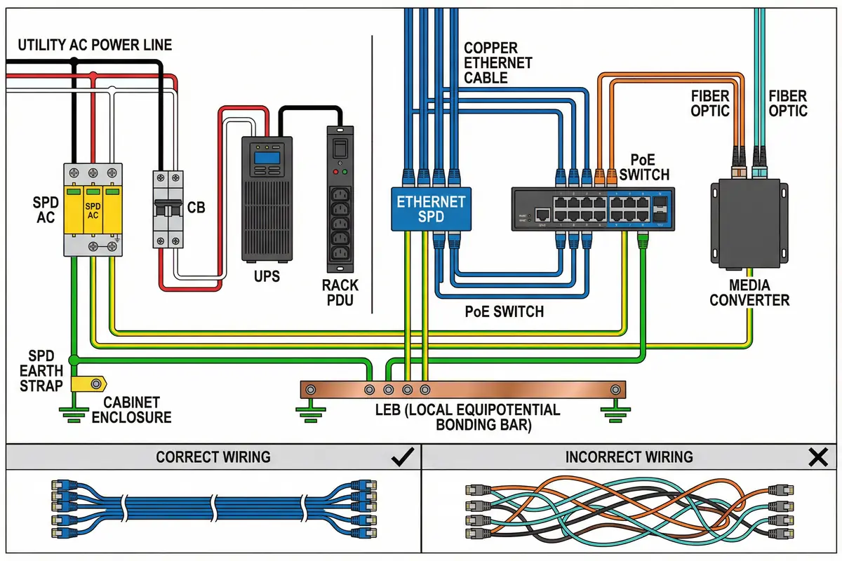
The equipment connection diagram illustrates the complete wiring arrangement for a typical field cabinet installation, showing the correct sequence and routing of all power, data, and bonding connections. The diagram emphasizes the critical importance of SPD placement — before sensitive equipment, not after — and the requirement for short, straight earth leads from SPD terminals to the LEB. The comparison between correct and incorrect wiring practices provides a practical reference for installation teams and quality inspectors.
Connection Sequence Requirements
The correct connection sequence for field cabinet wiring follows a strict order that ensures each protective element is in place before the next element that depends on it. For AC power, the sequence is: utility input → Type 2 SPD → circuit breaker → UPS (if present) → rack PDU → loads. The SPD must be installed before the circuit breaker, not after, to ensure that the breaker's overcurrent protection is not bypassed by the surge current path. For data connections, the sequence is: external copper cable → Ethernet SPD (bonded to LEB) → PoE switch → end devices. Fiber connections require no SPD but the media converter enclosure must be bonded to the LEB.
4.4 Business Logic & Exception Handling
The system's operational logic must account for both normal operating conditions and the exception scenarios that arise during and after lightning events. A well-designed exception handling workflow reduces mean time to recovery and prevents secondary failures caused by incorrect responses to surge-induced alarms or link flaps. The three primary exception scenarios are SPD failure, link instability during storms, and false alarm spikes — each requiring a distinct response workflow.
| Condition | Trigger / Detection | Immediate Response | Recovery Action | Verification |
|---|---|---|---|---|
| Normal operation | All SPD status normal; links stable | Continue monitoring | N/A | Periodic status check |
| SPD enters failure mode | Status contact change; visual indicator | System alarm to maintenance; log event | Replace SPD module; retest continuity | Status indicator normal; continuity test |
| Link flaps during storm | Link state change; packet loss spike | Failover to redundant path (ring) | Inspect route separation and bonding; correct if needed | Link stability; error counter baseline |
| False alarm spike | Alarm event rate exceeds KPI | Flag for investigation; do not disable sensors | Inspect shield grounding and cabinet bonding; correct terminations | Alarm rate returns to baseline |
| Post-strike downtime | Multiple device failures after storm | Activate incident response workflow | Replace SPDs; test grounding; restore services in priority order | Full system functional test; updated incident record |
Critical Exception: When a link flap occurs during a storm, the immediate response should be to failover to the redundant path — not to bypass the SPD for testing. SPD bypass testing should only be performed in a controlled manner during non-storm conditions, with appropriate safety precautions and documentation.