Chapter 5: Selection & Interfaces
Security Systems Lightning Protection and Grounding Design Guide
5.1 Core Product Overview
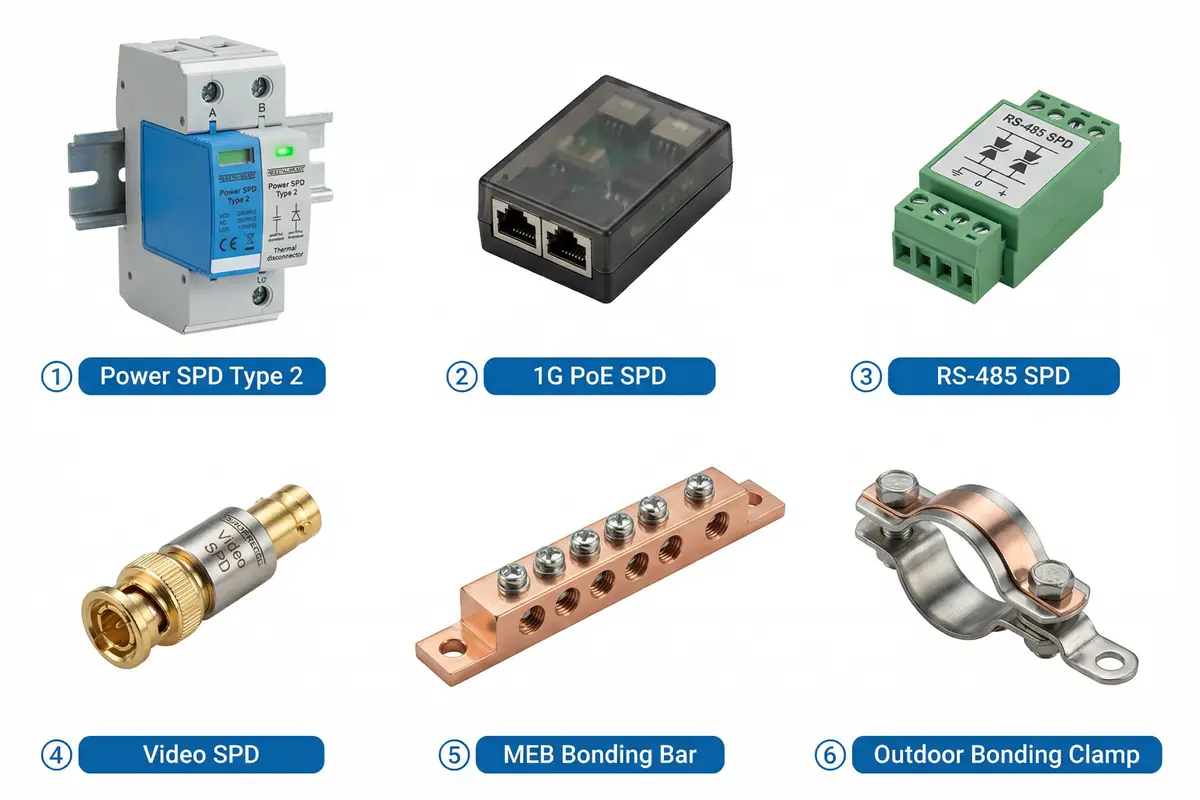
The core product range for security system lightning protection spans eight product categories, each addressing a specific interface type or protection function. Correct product selection requires matching the product's electrical parameters to the interface it protects, the environmental conditions at the installation location, and the maintenance strategy for the site. The photograph below shows representative products from each category, providing a visual reference for procurement and inspection teams.
5.2 Core Product Functions
Power SPD (DB / Cabinet)
The power SPD is the primary protection device for AC power lines entering the security system's distribution board or field cabinet. It must handle the full range of surge energies that can appear at its installation point, from switching transients to lightning-induced surges, while maintaining reliable operation under normal load conditions. The following functions define a compliant power SPD for security system applications.
- Surge diversion for L-N, L-PE, and N-PE protection modes (comprehensive mode coverage)
- Thermal disconnector with status indication (prevents overheating failure; provides visible fault signal)
- Replaceable cartridge design (preferred for maintainability; enables fast replacement without rewiring)
- Remote alarm contact output (optional; enables integration with BMS or monitoring system)
- Coordinated Up with downstream devices (ensures effective protection of connected equipment)
- Suitable for TN system type (TN-S or TN-C-S as applicable to the installation)
- High Imax/In rating per risk level (sized to survive multiple surge events without degradation)
- Clear labeling and DIN-rail mounting accessories (supports correct installation and maintenance)
PoE/Ethernet SPD
The PoE/Ethernet SPD protects the copper Ethernet links that connect IP cameras, access control devices, and other PoE-powered endpoints. It must pass both the data signal and the PoE power without degradation, while providing effective surge protection on all four pairs. Compatibility with the specific PoE class and data rate of the connected devices is a mandatory selection criterion.
- Supports required data rate (1G/2.5G as required by the network design)
- PoE class/current compatibility (verified against PSE and PD specifications)
- Low insertion loss and minimal return loss impact (preserves link margin)
- Multi-pair protection and common-mode handling (all four pairs protected)
- Chassis bonding design with shielded RJ45 connectors where applicable
- Replaceable modules preferred for maintainability
- Proper grounding terminal for short bonding conductor to LEB
- Outdoor-rated variant available for pole or cabinet installation
RS-485 / Alarm Loop / Control SPD
RS-485 and alarm loop SPDs protect the serial communication and dry-contact lines that connect access control readers, alarm detectors, and other control devices. These interfaces are particularly sensitive to surge damage because their signal voltages are low and their electronics are often directly connected to the communication lines without internal protection.
- Bidirectional line protection (protects both transmission directions)
- Low capacitance for signal integrity (critical for RS-485 at high baud rates)
- Correct clamping voltage for the interface (matched to signal voltage levels)
- Multi-mode protection (line-line and line-earth)
- Terminal block interface for easy service and replacement
- Shield/earth terminal management (proper termination of cable shields)
- Status indicator where available
- Clear wiring diagram to avoid polarity errors during installation
5.3 Technical Requirements
The table below presents the quantitative technical requirements for each product category, the typical parameter range, and the consequences of specification mismatches. These requirements must be incorporated into the procurement specification and verified during incoming inspection and acceptance testing.
| Item | Requirement (Quantitative First) | Typical Range | Mismatch Consequence |
|---|---|---|---|
| Power SPD Uc | ≥ nominal system max voltage | 275–320 V AC (example) | Nuisance tripping / overheating |
| Power SPD In/Imax | Sized by lightning risk level | In 20–40 kA; Imax 40–80 kA | Early failure in repeated storm events |
| Power SPD Up | Coordinated with downstream equipment | ≤ 1.5–2.5 kV | Downstream NIC/PSU damage |
| Ethernet SPD data rate | Meets or exceeds link speed | 1G / 2.5G | Link speed downgrade; packet loss |
| PoE current rating | Meets PSE output class | Per PoE class (15.4–90 W) | Overheating; PoE port reset |
| Control SPD capacitance | Low; per vendor specification | < 100 pF typical | Communication errors at high baud rates |
| Bond conductor size | Per code + risk level | 16–35 mm² Cu | High impedance path; flashover risk |
| Corrosion rating | Outdoor-rated for all exterior installations | 316L SS / bimetal | Bond failure over time; invisible protection gap |
Mismatch Consequences Summary
Specification mismatches between SPD parameters and the installation's actual conditions are a leading cause of both premature SPD failure and inadequate protection. The following consequences represent the most commonly observed failure modes from incorrect SPD selection or installation.
- SPD overheats and fails → fire risk or unprotected operation until replacement
- Up too high → NIC/PoE PHY damage on downstream devices despite SPD presence
- Data SPD incompatible with link speed → intermittent video loss or link downgrade
- Wrong grounding scheme → persistent false alarms from ground loop noise
- Undersized bonding conductor → flashover risk during high-energy surge events
- Corroded clamps → invisible bond failures that only manifest during storm events
5.4 Connection & Interface Design
The interface design for security system lightning protection must address eight distinct interface classes, each with its own electrical characteristics, SPD requirements, and compatibility considerations. Standardizing SPD footprints across the project reduces installation errors and simplifies maintenance. Vendor-verified PoE/SPD combinations should be used wherever possible to ensure compatibility under the full range of operating conditions.
| Interface Class | Connector Type | SPD Type | Key Compatibility Check | Replacement Strategy |
|---|---|---|---|---|
| AC power (230 V) | DIN rail terminal | Type 2 power SPD | Uc, In, Up, system type (TN-S/TN-C-S) | Hot-swap cartridge; spare on site |
| DC power (12/24/48 V) | Terminal block | DC power SPD | Uc ≥ DC bus voltage; polarity correct | Replaceable module |
| PoE Ethernet (1G/2.5G) | RJ45 in/out | PoE/Ethernet SPD | Data rate; PoE class; insertion loss | Inline module; spare on site |
| Fiber optic | LC/SC/ST | None (enclosure bonded) | Fiber type; connector type; link loss | Media converter replacement |
| RS-485 serial | Terminal block (A/B/GND) | RS-485 SPD | Capacitance; clamping voltage; polarity | Terminal block module |
| Dry contact alarm loop | Terminal block | Control line SPD | Clamping voltage; loop resistance | Terminal block module |
| Coax video (75 Ω) | BNC / F-type | Coax SPD | Impedance match; insertion loss | Inline coax module |
| Audio / intercom | Terminal block | Audio line SPD | Impedance; frequency response | Terminal block module |
5.5 Typical Wiring & Interface Logic
The wiring and interface logic diagram below illustrates the correct connection approach for each of the four primary interface types: AC power, PoE Ethernet, RS-485, and fiber. The diagram highlights the critical requirement that SPD earth terminals must be connected to the LEB with the shortest possible straight conductor — coiled or long earth leads significantly reduce the SPD's effectiveness by adding inductance to the surge current path.
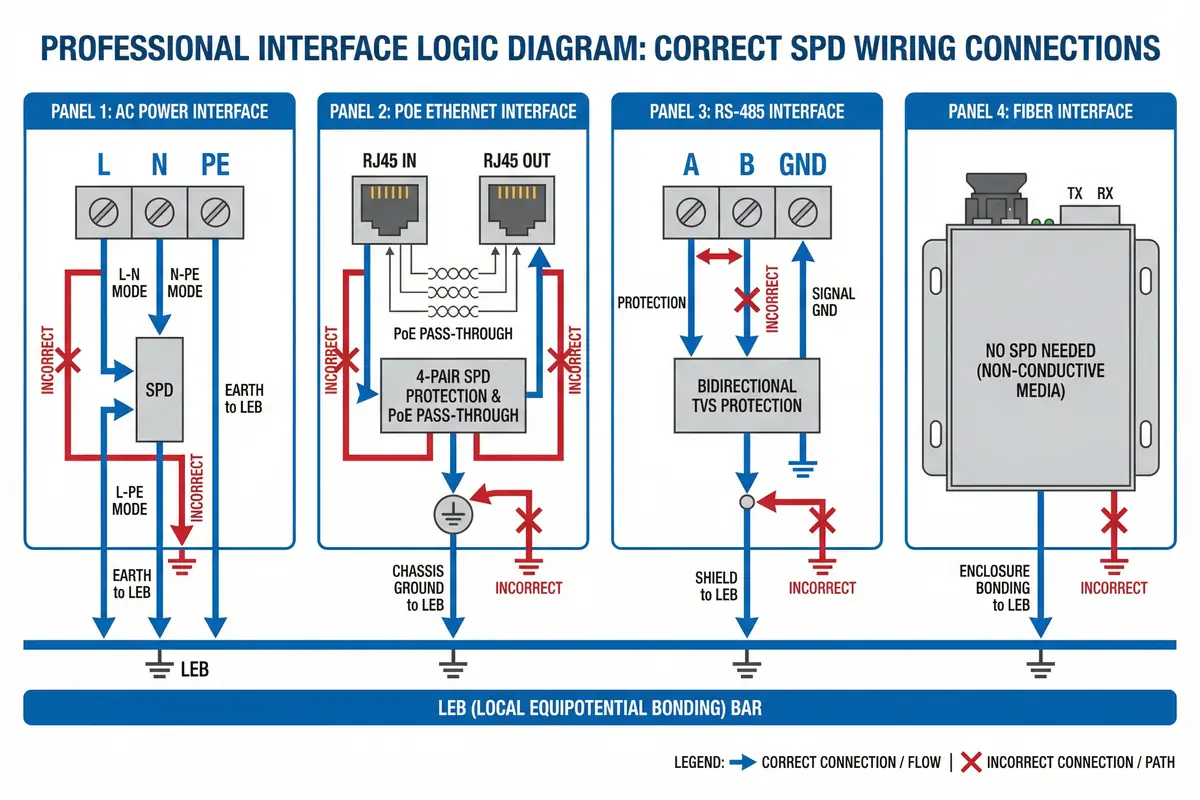
Common Wrong Wiring Practices
- SPD placed far from the cable entry point (long lead between entry and SPD defeats protection)
- Ground lead coiled or routed in a long loop (adds inductance; reduces clamping effectiveness)
- SPD installed after sensitive device instead of before (device is unprotected)
- Cabinet not bonded to LEB; SPD "earth" effectively floating
- Shield grounded at both ends without a planned strategy (creates ground loops)
- RS-485 polarity reversed at SPD terminals (communication failure)
- PoE SPD used on non-PoE or wrong PoE class without verification (overheating, port reset)
- Mixing PE with signal reference improperly (noise injection into signal circuits)
Troubleshooting & Fix Guide
| Symptom | Likely Cause | Diagnostic Step | Fix | Verification |
|---|---|---|---|---|
| SPD status indicator red/fault | SPD module degraded or failed | Check indicator; measure Uc | Replace SPD module | Status normal; continuity test |
| Bonding continuity fail | Loose lug, corroded clamp, missing jumper | Micro-ohmmeter from cabinet to MEB/GES | Retorque or replace connection | Continuity < 0.1 Ω |
| Long SPD lead | Incorrect routing during installation | Visual inspection; measure lead length | Reroute to shortest path; < 0.5 m preferred | Visual; lead length < 0.5 m |
| Ethernet link negotiates at lower speed | SPD insertion loss too high; wrong SPD type | Bypass SPD briefly (controlled test) | Replace with compatible SPD model | Link at correct speed; no errors |
| PoE port overheating / reset | PoE SPD current rating insufficient | Measure port current; check SPD rating | Replace with correct PoE class SPD | Port temperature normal; stable PoE |
| Shield termination causing noise | Unplanned both-end shield grounding | Review shield termination points | Correct to intended strategy (single or both-end) | Noise level within spec; alarm rate normal |
| Tray bonding continuity fail | Missing jumper at tray joint | Continuity test along tray run | Add bonding jumper at joint | Continuity < 0.1 Ω end-to-end |
| Persistent false alarms | Ground loop or poor cabinet bonding | Inspect shield points; measure cabinet continuity | Correct terminations; bond cabinet to LEB | False alarm rate returns to baseline |